Reasons for using the LTM-2 for pulp level monitoring and measurement include:
1. Mechanical measuring devices such as float balls and ultrasonic targets can become covered with solids causing the device to hang up, become heavy and sit in the slurry deeper and/or the slide mechanism can get jammed and stuck preventing smooth operation.
2. Slurry density (% solids) fluctuations cause float and pressure differential devices to vary. Changing slurry apparent specific gravity will cause the float ball to ride higher or lower in the slurry, even if the slurry level stays constant. Pressure differential devices such as bubble tubes and pressure differential electronic sensors measure based on slurry weight above the device, so pulp level readings will vary as slurry densities change.
3. Basic froth mechanics, particularly in flotation cells, where bottom layers of the froth bed will be quite wet because fine bubbles coursing upward to the froth will push entrained slurry into the froth. As the fine bubbles coalesce into larger bubbles and rise to the top of the froth bed, this slurry drains back into the cell. When froth characteristics or operating conditions change, the amount of water and slurry in the bottom layers of the froth will vary and make proper froth-slurry interface depth measurement more problematic.
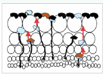
Point #3 is worth dwelling on because this is often overlooked or not well understood. A rough representation of a mineral flotation froth cross section is provided below. The fine bubbles generated by the flotation cell impeller rise to the bottom of the froth bed and coalesce into larger bubbles as these rise in the froth. The values are upgraded as the bubbles coalesce because the bubble surface area decreases with the result being less particle carrying capacity. Probabilistically the weakest, least hydrophobic particles are released and drain back into the cell.
There is a massive amount of air in a flotation cell, typically 12-25% of a float cell’s total volume, which rises enmass to the froth layer as fine bubbles. Much slurry is pushed into the lower froth bed which is held in the voids between the bubbles until the slurry can drain back into the cell. As illustrated in the figure, there is more slurry in the lower froth bed than higher due to drainage.
This slurry in the void spaces between the bubbles must and will drain to the float cell. However there will be some slurry holdup before draining which can make the pulp-froth interface indistinct and difficult to define depending on the amount of slurry held in the froth. The amount of slurry carried into the froth can significantly vary.
Mechanical and pressure differential slurry level measuring techniques can have difficulties consistently and precisely monitoring the pulp-froth interface level under these conditions. However, pulp level measurement techniques can more effectively and consistently define the froth-pulp level interface height.
The LTM-2 pulp level monitoring probe technology dramatically reduces the complication of slurry level interface monitoring under a wide range of froth and flotation conditions. Because the probe is quite sensitive, it capably and consistently measures at very low slurry (e.g. water) concentrations, it is possible to define the slurry-froth interface level as the precise point where there is insufficient slurry to conduct an electrical current.